PervapDesign
PervapDesign Website
This not-for-profit website provides details of short-cut methods for the design of hydrophilic pervaporation systems using simple equations.These methods should facilitate consideration of pervaporation in process feasibility studies and front-end design as well as being of use to researchers and undergraduate students.
Design Approach
-
The design approach is to size an ideal system. The optimum number of stages is determined by comparing the membrane area required for a multi-stage system with that of an isothermal system.
Finally the area is adjusted upwards to allow for inefficiencies.
Process Data
-
There is little data pertaining to industrial-scale pervaporation available. Further research is required as regards actual membrane area efficiency and energy consumption - e.g. kg steam per kg aqueous permeate.
Contact from those involved in industrial-scale pervaporation systems is welcome.
Pervaporation Membrane Index
-
A novel metric the “Pervaporation Membrane Index” is outlined: it provides appropriate weighting to both flux and separation with respect to industrial operations.
Analysis of lab trial data
-
An analytical equation for isothermal pervaporation systems is shown. It can be re-arranged for analysis of batch isothermal systems such as are typically used for laboratory trials: concentration versus time relationship can be predicted.
Contact Details
-
Cilian Ó Súilleabháin lectures in Chemical and BioPharmaceutical Engineering at Cork Institute of Technology, Ireland. He completed his PhD entitled "Modelling of Hydrophilic Pervaporation Systems" at Dublin City University
in 2019 under the supervision of Dr. Greg. Foley.
e-mail: mail.pervapdesign.eu
PhD thesis
-
The PhD "Modelling of hydrophlic pervaporation systems" can be obtained from the DCU library.
A pdf copy can be downloaded via this link
PhD thesis
Modelling of hydrophilic pervaporation systems
Dr. Cilian Ó Súilleabháin, Cork Institute of Technology.An ethanol solution containing 4 wt. % water is an azeotrope: the vapour has the same composition as the liquid when boiled. Such mixtures cannot be separated by standard distillation systems. Half the solvents recovered in Ireland form azeotropes.
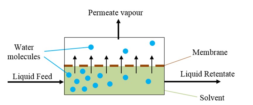
Pervaporation uses a membrane to separate such mixtures. Hot liquid feed enters a membrane module, aqueous permeate vaporises and passes through the membrane and the remaining solvent-rich liquid leaves as liquid retentate. Pervaporation is usually used in conjunction with distillation and achieves significant energy savings.

The author developed equations that allow the membrane area to be calculated for industrial pervaporation systems where water is removed from solvents such as ethanol and isopropanol. This research was the subject of the author’s PhD thesis which was supervised by Dr. Greg Foley of DCU.
Multi-stage adiabatic systems


Constant permeate concentration across a range of liquid concentrations is assumed. This was validated by analysis of data in peer-reviewed publications relating to commercial membranes.
Isothermal Pervaporation Analytical Equation
An exact analytical expression was derived for the average flux in ideal isothermal pervaporation modules where flux is proportional to concentration.
This simple equation only requires readily available data. It provides a benchmark when deciding the number of stages to be used in a multi-stage system.
The expression can be modified so as to predict the progress of isothermal batch operations.
This provides a simpler and more accurate method for determining flux from bench-scale isothermal trials than was available heretofore.

Adiabatic systems where flux is independent of concentration
There are a small number of systems where flux is independent of concentration. Eq. (2), an analytical expression, was derived for such systems. Eq. (3) is a simple short-cut equation for such systems that is accurate to 1.1% for the full range of industrial applications and solvents for which pervaporation is used industrially.


Adiabatic systems where flux is proportional to concentration
No analytical solution was found for the more common case of adiabatic pervaporation where flux is proportional to concentration.
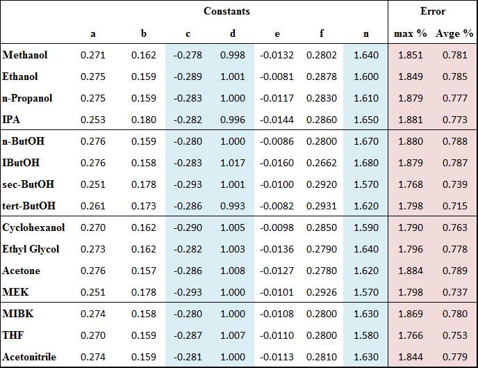
A short-cut equation, Eq. (4) was developed for 14 solvents including ethanol and isopropanol. The constants vary depending on the solvent. In all cases the maximum error is less than 1.9% and the average error is less than 0.8%.

Membrane Area Efficiency
The equations above model ideal systems. A larger membrane area is required for actual pervaporation systems. Thus an “area efficiency” akin to the Murphree efficiency in distillation systems is required.
For the first time, efficiency values for industrial-scale systems were calculated using data from published literature: efficiencies of 70-76% were determined for three runs at an industrial-scale pilot plant.
This corresponded with theoretical models.
Optimisation of multi-stage systems
Optimisation of ideal multi-stage dehydration systems were reviewed. Minimum overall area is achieved by having successively larger areas for later stages.
A novel short-cut method for minimising the area of ideal systems was developed.
Typical systems have equally-sized membrane for all stages: it was found that this does not lead to significant increases in overall membrane area.
Use of different types of membrane within a single system can improve performance. High selectivity membranes for the earlier stages followed by high flux membranes with lower selectivity for later stages can lead to significant reductions in overall membrane area. There is little loss in the overall system selectivity as the flux in the later stages is low.
Pervaporation Membrane Index
A new single metric, “The Pervaporation Membrane Index”, Eq. (5), was developed that provides appropriate weighting to both flux and separation.
It is defined as the average flux such that the water content reduces from 1% w/w above to 1% w/w below the azeotropic concentration, multiplied by the pervaporation separation modulus.
The current combined metric, the PSI, gives to much weight to separation and not enough to flux. The PMI addresses this issue and thus should encourage the development of membranes with higher fluxes.

A new energy consumption metric was developed: kg steam consumed per kg water removed in the permeate stream. Three industrial plants used 1.88 - 2.20 kg steam per kg water removed. One pilot plant with steam recovery consumed 1.37 kg steam per kg water removed. This metric is independent of the solvent being recovered and the feed concentration. It will thus facilitate benchmarking of industrial operations and provides a simple short-cut estimate of energy consumption for pervaporation systems.
Conclusion
The ideal models and novel metrics developed in this work provide a major step towards the development of simple design methods for pervaporation systems.
Assumptions in this work are justified by reference to peer-reviewed publications relating to commercial membranes and industrial-scale pervaporation systems.
The new energy metric allows rapid estimation of the likely energy consumption for pervaporation systems and for benchmarking different pervaporation plants.
The research will be of benefit to engineers working in industry, particularly those who are new to the field of pervaporation. The short-cut design methods will facilitate consideration of pervaporation in process feasibility analyses and front-end design, albeit that more rigorous design methods are required for the subsequent detailed design of pervaporation systems. The availability of such short-cut methods should increase the adoption of pervaporation in industry. The short-cut methods will also be of use for the analysis of modules and system design parameters by undergraduate students.
Further research will be undertaken to obtain efficiency and energy consumption data for industrial systems.
Constants for Eqn 4
